

|
EIDORS: Electrical Impedance Tomography and Diffuse Optical Tomography Reconstruction Software |
|
EIDORS
(mirror) Main Documentation Tutorials − Image Reconst − Data Structures − Applications − FEM Modelling − GREIT − Old tutorials − Workshop Download Contrib Data GREIT Browse Docs Browse SVN News Mailing list (archive) FAQ Developer
|
Simulation of 3D surface electrode patterns.Simulate 3D data
shape_str = ['solid top    = plane(0,0,0;0,0,1);\n' ...
             'solid block  = orthobrick(-4,-4,-2;4,4,2) -maxh=0.3;\n' ...
             'solid ball   = sphere(1,-1,-1;0.2); tlo ball;\n' ...
             'solid mainobj= top and block and not ball;\n'];
[epos_x,epos_y] = meshgrid(linspace( -2,2,5),linspace(-2,2,5));
elec_pos = [epos_x(:), epos_y(:), ones(size(epos_x(:)))*[0,0,0,1] ];
elec_shape=[0.1];
elec_obj = 'top';
fmdl = ng_mk_gen_models(shape_str, elec_pos, elec_shape, elec_obj);

stim = mk_stim_patterns(size(fmdl.electrode,2), 1, ... %rings
    [0,7], [0,7], {'no_meas_current'},1);

fmdl.stimulation = stim;
img= mk_image(fmdl,1);
img.elem_data(fmdl.mat_idx{1}) = 2;

show_fem(img); view(-16,22); set(gca,'Projection','perspective')
print_convert surface_sim01a.png '-density 100'
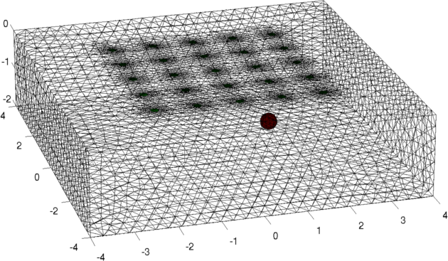
Figure: model of a conductive ball underneath a set of electrodes vi = fwd_solve(img); img.elem_data(:) = 1; vh = fwd_solve(img); vi = add_noise(5, vi, vh); %SNR=5 Create 3D forward model and reconstruction model
shape_str = ['solid top    = plane(0,0,0;0,0,1);\n' ...
             'solid block  = orthobrick(-4,-4,-2;4,4,2) -maxh=0.3;\n' ...
             'solid mainobj= top and block;\n'];
fmdl = ng_mk_gen_models(shape_str, elec_pos, elec_shape, elec_obj);
fmdl.stimulation = stim;

% inverse model: a smaller region directly over the electrodes with coarser mesh
shape_str = 'solid mainobj= orthobrick(-3,-3,-2.0;3,3,-0.2) -maxh=0.5;';
cmdl = ng_mk_gen_models(shape_str, [], [], '');

% define the mapping between the two meshes
c2f= mk_coarse_fine_mapping( fmdl, cmdl);

% set the reconstruction parameters
inv3d= select_imdl(fmdl, {'Basic GN dif'});
inv3d.solve= @inv_solve_diff_GN_one_step;
inv3d.hyperparameter.value = .03;
inv3d.RtR_prior= @prior_laplace;
inv3d.fwd_model.coarse2fine = c2f;
inv3d.rec_model = cmdl;

hh= show_fem(cmdl); set(hh,'EdgeColor',[0,0,1]);
hold on; show_fem(fmdl); hold off
view(-16,22); set(gca,'Projection','perspective')
print_convert surface_sim03a.png '-density 100'
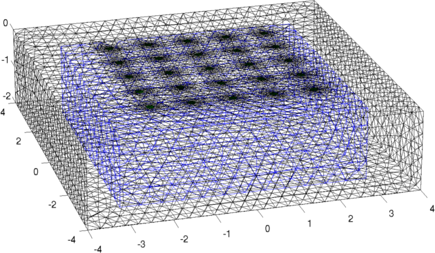
Figure: Forward model (black) and reconstruction model (blue) Inversion (using a difference solver)imgr = inv_solve(inv3d, vh, vi); show_fem(imgr); view(-16,22); set(gca,'Projection','perspective') print_convert surface_sim04a.png '-density 100' % Set levels for z-intercepts of -0.4,-1.0,-1.6 levels= [inf,inf,-0.4,1,1; inf,inf,-1.0,2,1; inf,inf,-1.6,3,1]; show_slices(imgr,levels) print_convert surface_sim04b.png '-density 150' % Try a different prior inv3d.RtR_prior= @prior_noser; inv3d.prior_use_fwd_not_rec = 1; inv3d.hyperparameter.value = .3; imgr = inv_solve(inv3d, vh, vi); show_fem(imgr); view(-16,22); set(gca,'Projection','perspective') print_convert surface_sim04c.png '-density 100' show_slices(imgr,levels) print_convert surface_sim04d.png '-density 150' 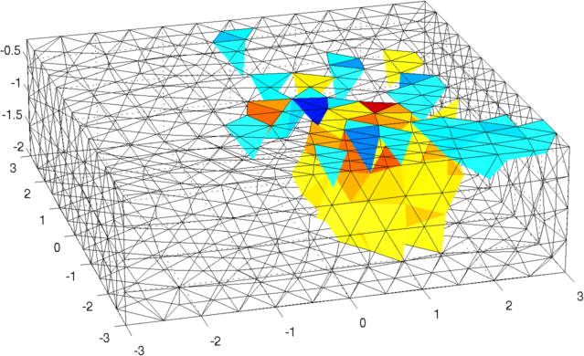
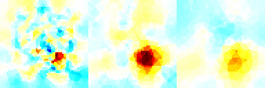
Figure: Reconstruction: (top) mesh and (bottom) slices at z=-0.4, z=-1.0, and z=-1.6. < 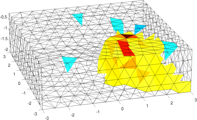
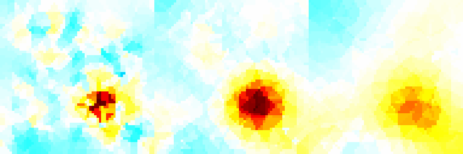
Figure:Reconstruction with a NOSER prior. |
Last Modified: $Date: 2017-02-28 13:12:08 -0500 (Tue, 28 Feb 2017) $ by $Author: aadler $