|
|
EIDORS: Electrical Impedance Tomography and Diffuse Optical Tomography Reconstruction Software |
|
EIDORS
(mirror) Main Documentation Tutorials − Image Reconst − Data Structures − Applications − FEM Modelling − GREIT − Old tutorials − Workshop Download Contrib Data GREIT Browse Docs Browse SVN News Mailing list (archive) FAQ Developer
Hosted by |
GREIT evaluation: Evaluation using simulation dataIn order to test the performance of GREIT, we create a set of simulation data. Here we look at the performance for an object moving radially toward the side from the centre of the medium.Algorithms to testFirst, run the matlab command>> addpath ../GREIT-algorithmto give matlab access to the algorithms folder. Use the function In the rest of this example, the function get_list_of_algs.m lists the provided algorithms to test.
% Algorithm list $Id: get_list_of_algs.m 1619 2008-09-22 16:32:56Z aadler $
function algs= get_list_of_algs;

algs = {'GREIT_Sheffield_backproj', ...
        'GREIT_NOSER_ndiff', ...
        'GREIT_NOSER_diff', ...
        'GREIT_test_ndiff', ...
       };
Prepare simulation data: phantom dataHere we can use either:
Tests: position, amplitude, resolution, PSFThese parameters are calculated from an image as illustrated in the following figure. The key calculation is the Half Maximum Set (HMS), which contains all pixels above half the maximum value.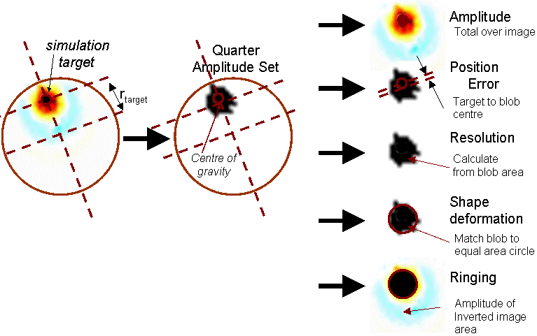
Calculation of parameters for reconstructed images: Amplitude, Position Error, Resolution, Shape Deformation Ringing Calculate Half-Maximum SetThe function calc_hm_set.m calculates the HAS from each imagefunction hm_img = calc_hm_set(img,frac) % hm_img= CALC_HA_SET(img) % hm_img is 32x32xNimg. It is 1 inside the Half Ampl Set % frac is the fraction of maximum (0.5 or 0.25) % hm_img expects conductive changes. Use calc_hm_set(-img,frac) for non-c % (C) 2008 Andy Adler. Licenced under GPL v2 or v3 % $Id: calc_hm_set.m 1598 2008-07-30 10:17:24Z aadler $ [x,y]=meshgrid(linspace(-1,1,32),linspace(-1,1,32)); map = x.^2+y.^2<1.1; hm_img = logical(zeros(size(img))); for i=1:size(img,3); imi = img(:,:,i); imi= imi(map); hmi= logical(zeros(32)); hmi(map) = imi >= (max(imi) * frac); hm_img(:,:,i) = hmi; end Reconstruct example imagesFirst, we reconstruct an image using some of the proposed algorithms.
% Reconstruct some images $Id: simulation_test03.m 1621 2008-09-22 18:09:43Z aadler $
load sim_radmove_homog.mat

imb.calc_colours.ref_level = 0; % select colour output
imb.calc_colours.greylev   = 0.01; % black backgnd
bkgnd= [.1,.5,.1]; imb.calc_colours.backgnd   = bkgnd;

idx= 157; dir='simulation_test_imgs';

phi = linspace(0,2*pi,10);
xc=-xyzr_pt(1,idx) + xyzr_pt(4,idx) * sin(phi); xc= round(xc*15.5 + 16.5);
yc=-xyzr_pt(2,idx) + xyzr_pt(4,idx) * cos(phi); yc= round(yc*15.5 + 16.5);
ind= sub2ind([32,32],yc,xc);

% Use this Map for reconstruction shape
[x,y]=meshgrid(linspace(-1,1,32),linspace(-1,1,32)); out = x.^2+y.^2>1.1;

algs = get_list_of_algs;
for i= 1:length(algs)
   img = feval(algs{i}, vh, vi(:,idx) );
   hmi = calc_hm_set( img, 0.5 )+1;
   qmi = calc_hm_set( img, 0.25 )+1;

   imc= calc_colours(img, imb);
   imc(out) = 1; hmi(out) = 3; qmi(out) = 3; % background
   imc(ind) = 1; hmi(ind) = 3; qmi(ind) = 3; % target

   imwrite(imc,colormap, sprintf('%s/simulation_test03_%d.png',dir,i),'png')
   clrmap = [0,0,0;1,1,1;bkgnd];
   imwrite(hmi,clrmap, sprintf('%s/simulation_test03_h%d.png',dir,i),'png')
   imwrite(qmi,clrmap, sprintf('%s/simulation_test03_q%d.png',dir,i),'png')
end
Calculate parameters from imagesThe parameters listed previously are calculated from images using the function GREIT_sim_params.m.function params = GREIT_sim_params(imgs, xyzr_pt) % params = GREIT_sim_params(imgs) % params(1,:) = Image Amplitude % params(2,:) = Position Error => + toward centre, - toward edge % params(3,:) = Resolution % params(4,:) = Shape Deformation % params(5,:) = Ringing % (C) 2008 Andy Adler. Licensed under GPL v2 or v3 % $Id: GREIT_sim_params.m 1590 2008-07-29 11:23:55Z aadler $ N_imgs = size(imgs,3); for i= 1:N_imgs [xmean,ymean,equiv_circ,map,qmi,img] = calc_cofg(imgs(:,:,i)); params(1,i) = calc_amplitude( img ); params(2,i) = calc_posn_error( qmi, xmean, ymean, xyzr_pt(1:2,i) ); params(3,i) = calc_resolution( qmi, map ); params(4,i) = calc_shape_deform( qmi, equiv_circ ); params(5,i) = calc_ringing( img, qmi ); end % TODO: Fix this when we start to care about units params(1,:) = params(1,:)/mean(params(1,1:10)); function ampl = calc_amplitude(img) ampl = sum(img(:)); function pe = calc_posn_error(qmi, xmean, ymean, xy) pe = sqrt(sum(xy.^2)) - sqrt( xmean^2 + ymean^2); function res = calc_resolution(qmi, map) res = sqrt( sum(qmi(:)) / sum(map(:))); function sd = calc_shape_deform(qmi, equiv_circ) not_circ= qmi & ~equiv_circ; sd = sum(not_circ(:))/sum(qmi(:)); function rr = calc_ringing(img, qmi ); ring_part = img .* ( (img<0) & ~qmi); rr = -sum( ring_part(:) )/sum( img(:).*qmi(:) ); function [xmean,ymean,equiv_circ,map,qmi,img] = calc_cofg(img); % if abs(max(img(:))) < abs(min(img(:))); img= -img; end qmi = calc_hm_set( img, 0.25 ); if sum(img(:) & qmi(:))<0 ; keyboard ; end [x,y]=meshgrid(linspace(-1,1,32),linspace(-1,1,32)); map = x.^2+y.^2<1.1; qmi = qmi.*map; img = img.*map; ss_qmi = sum(qmi(:)); xmean = sum(sum( (qmi.*x) ))/ss_qmi; % centre of gravity ymean = sum(sum( (qmi.*y) ))/ss_qmi; equiv_circ = (x-xmean).^2 + (y-ymean).^2 < ss_qmi/pi/(32/2)^2; Calculate noise performanceNoise parameters are based on the Noise Figure which estimates the amplification of noise through the reconstruction algorithm (as a function of radial position).The desired Noise Figure should be as low as possible. Noise sources include: 1) Pseudo-random Gaussian noise, and 2) Measured phantom noise (from Hahn et al, 2008). 
Calculation of noise parameters for reconstructed images. Note that the l1 norm is used for clarity in the figure. Other norms are possible: function params = GREIT_noise_params(imgs, alg, vh, vi ) % params = GREIT_noise_params(imgs, homg_voltage, sig_voltage) % params(1,:) = Noise Figure % (C) 2008 Andy Adler. Licensed under GPL v2 or v3 % $Id: GREIT_noise_params.m 1622 2008-09-26 14:06:17Z aadler $ % There are better ways here noise = 0.01*std(vh)*randn(208,1000); vhn= vh*ones(1,size(noise,2)); %signal_y = vi - (vh*ones(1,size(vi,2))); signal_y = vi ./ (vh*ones(1,size(vi,2))) - 1; %noise_y = mean(std(noise ),2); noise_y = mean(std(noise./vhn ),2); snr_y = mean(abs(signal_y),1) / noise_y; im_n= feval(alg, vh, vhn + noise); %signal_x = mean(mean(abs(imgs),1),2); signal_x = mean(mean( (imgs),1),2); %noise_x = mean(abs(im_n(:))); noise_x = mean(std(std(im_n))); snr_x = signal_x / noise_x; params= [snr_y(:)./snr_x(:)]'; Parameters from example imagesIn order to display the parameters from the example images, we calculate:
% Calc Parameters $Id: simulation_test04.m 6446 2022-12-02 12:14:47Z aadler $
subplot(421); algs = get_list_of_algs;
for i= 1:length(algs)
img = feval(algs{i}, vh, vi );
param= [GREIT_noise_params(img, algs{i}, vh, vi); ... % noise parameters
GREIT_sim_params( img, xyzr_pt)]; % image parameters
for j=1:size(param,1)
plot(param(j,:));
set(gca,'XTickLabel',[]); set(gca,'XLim',[1,size(param,2)])
if j==1; set(gca,'YLim',[0,3.5]); % Noise Figure
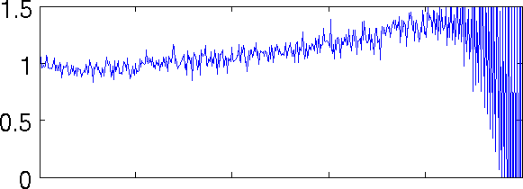
elseif j==2; set(gca,'YLim',[0,1.5]); % Amplitude
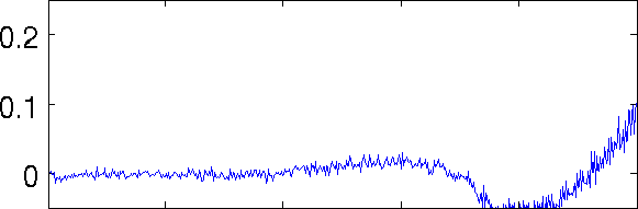
elseif j==3; set(gca,'YLim',[-0.05,0.25]); % Posn Error
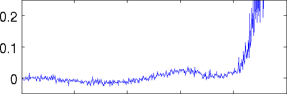
elseif j==4; set(gca,'YLim',[0,0.4]); % Resolution
elseif j==5; set(gca,'YLim',[0,0.5]); % Shape Deform
elseif j==6; set(gca,'YLim',[0,1.5]); % Ringing
end
print('-dpng','-r200',sprintf('simulation_test_imgs/simulation_test04_%d%d.png',i,j));
print('-dpng','-r100',sprintf('simulation_test_imgs/simulation_test04sm_%d%d.png',i,j));
end
end
system('find simulation_test_imgs -name s*0*_??.png -exec convert -trim "{}" png8:"{}" ";"')
|
Last Modified: $Date: 2017-02-28 13:12:08 -0500 (Tue, 28 Feb 2017) $ by $Author: aadler $